Electric vehicle charging facilities are important for the development of electric vehicles as they can reduce the energy storage of on-board batteries. The limited battery capacity of an electric vehicle determines the limited driving range of an electric vehicle. We simulated and tested a typical EV on-board charger. The simulation of the charger was done by the power simulation software PSIM. We hope that this research will contribute to the further development of facilities for on-board charging systems.
As people are becoming more aware of the environmental hazards associated with carbon emissions, they are also looking for ways to make renewable energy available for transport. With this in mind, the automotive industry has also begun to produce and plan for electric and hybrid vehicles in the long term.
In this era of climate change and environmental warming, electric cars not only have many economic advantages but are also very beneficial from an environmental point of view. The advent of electric vehicles is also driving manufacturers to undertake related research and development, as well as promoting charging facilities scattered around cities.
Electric vehicles will also enable us to reduce our dependence on fossil fuels and make renewable energy our preferred source of energy. This will also have a positive impact on the environment by reducing the emissions that contribute to global warming.

The growth in the use of electric vehicles over the next decade will be linked to several important factors. These factors include international standards for electric vehicles, common charging station standards, common ancillary equipment, and user-friendly applications. A number of organisations have already been formed to introduce these standards, including the International Energy Agency (IEA), the Society of Automotive Engineers (SAE), and the Institute of Electrical and Electronics Engineers (IEEE).
Electric vehicle charging stations are also urgently needed, as a sufficient number of these facilities can reduce the amount of capacity needed for on-board batteries. The limited driving range of an electric vehicle is largely limited by the capacity of the battery, which can also be solved by constructing charging stations at important points. As a result, some savings can be made in the cost of equipping batteries.
Standards for electric vehicle charging systems are likewise a very important factor. By applying these standards, the charging infrastructure in public places will certainly be recognised and will also create a good interaction between the users and the technology used. From an economic point of view, these will also reduce manufacturing costs.
Conductive charging system
The charging system of an electric vehicle must fulfil two basic functions. They are two electrical functions and one mechanical function. The batteries of an electric vehicle at DC voltage are different depending on the rated voltage, the state of charge, and the charging and discharging rates. The first electrical function is to rectify the AC voltage to DC voltage, and the second electrical function is to regulate the battery voltage so that the charge and discharge rates match the battery characteristics. Both of these electrical functions are necessary for a charger to have. The latter, the mechanical function, is to enable the EV to be adapted to the electric vehicle and the electric vehicle charging equipment (EVSE).
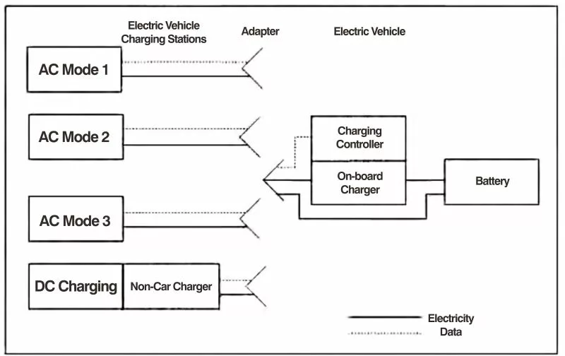
The conductive charging system consists of a charger and an adapter. There are two types of chargers, an on-board charger (OBC) and a non-on-board charger. The on-board charger is permanently mounted on the vehicle, while the non-on-board charger is not mounted on the vehicle.
Regardless of whether the connector is grounded or not, electric vehicle charging equipment is a good conductor, with accessories, electrical equipment, and switches mounted to ground. The electric vehicle charging equipment is known as a charging station. The structure of a charging station is shown in Figure 1.

Fig. 1 Conductive charging system structure
The standard of conductive charging system includes several parts. Charging level, charging station, sockets, connectors, communication protocols, charger type, battery and electric vehicle. In this article, we have chosen a part of standards to study and they are charging levels, sockets, charging stations, connectors, pilot control and on-board chargers.
According to SAE J1772, there are 3 levels of charging methods:
Level 1: The charging method is that the electric vehicle is charged via a standard electrical outlet (NEMA 5-15R) with a maximum current of 12A and a rated voltage of 120V single phase AC. The on-board charger has a capacity of approximately 1.9kW.
Level 2: Charging is done by charging the EV through an Electric Vehicle Charging Station (EVSE) with a maximum current of 32A, single-phase AC rated at a maximum elegance of 40V.
Direct current (DC) charging: The charging method is that the vehicle is charged via a DC and non-vehicle-supplied electric vehicle charging station (EVSE).
The charging method is that the car is charged by a DC and non-vehicle charger supplied by the EVSE, with a maximum current of 400A and a maximum voltage of 600V DC.
The maximum current can be up to 400A and the maximum voltage up to 600V DC.
The fact that EVs should be fitted with on-board chargers (OBCs) and the prospect of EVs in the future makes it desirable for OBCs to fulfil the following criteria:Single-phase input;High efficiency;Low harmonics;Almost uniform power factor;Inexpensive;Small size and light weight;Safe operation;
A power factor regulator that meets the IEC1000-3-2 standard is required to regulate the line current harmonics. Based on the above considerations, the overall block diagram of an on-board charger (OBC) should include a PFC converter and a DC / AC converter. Input filters are also required to prevent harmonics and noise from entering the distribution lines. To meet safety standards, there should also be isolation between the output of the charger and the power supply. The overall block diagram of the vehicle charger is shown in Fig 2.

Fig. 2 Block diagram of a typical OBC module
Power Factor Conditioner Simulation
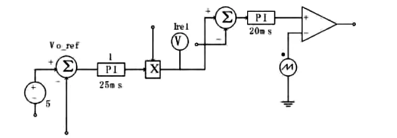
The simulation has been carried out for the power factor regulator (PFC) of the on-board power supply (OBC). The power supply circuit (Fig. 3) consists of an IGBT and a control circuit (Fig. 4) to demonstrate the functioning of the power factor regulator to generate sinusoidal input current and regulate in-phase with the line voltage.

Fig. 3 PFC circuit

Fig. 4 PFC Control Circuit

Fig. 5 Input Voltage and Input Current
Fig. 5 shows the input current and line voltage of the car charger. It can be seen that the current is in-phase with the voltage, i.e. almost unit power factor.

Figure 6 OBC Test Block Diagram
Table 1 Measured parameters | ||||
| Summary | Voltage | Current | ||
| Frequency | 50 | RMS | 220 | 6.55 |
| Power | Peak | 303 | 9.36 | |
| kW | 1.43 | Peak | 1.38 | 1.43 |
| KVA | 1.44 | Harmonic RMS | 3 | 4.4 |
| KVar | 0.16 | |||
| Peak power | 2.83 | |||
| Total Power Factor | 0.99 | |||
| Dynamic Power Factor | 0.99 | |||
Conclusion
We draw the following conclusions:The EV conductive charging system of Mode 1 consists of an adapter and an on-board charger (OBC), i.e., it is an in-vehicle charger placed in the vehicle.
The configuration of the power factor regulator plays an important role in improving the input power quality of the charger due to the increased efficiency of the charging.
The tests of the on-board charger proved that the on-board charger is a two-stage converter, where the first stage, i.e., the power factor regulator, has a power factor value approximately equal to one.
