The DC/DC converter is an important component of electric vehicle (EV) chargers, and it is also one of the main interference sources affecting the electromagnetic environment of EV chargers. Aiming at the common-mode electromagnetic interference (EMI) generated by the DC/DC converter in the charger, a voltage-complementary phase-shifted ZVS-DC/DC full-bridge converter with clamping diode is proposed to suppress the common-mode EMI generated by the converter based on the sources and propagation paths of the EMI.
Firstly, the working principle of the buck-type DC/DC full-bridge converter in a charger and the main EMI interference sources are analyzed, secondly, the common-mode EMI propagation path of the DC/DC converter is modeled and theoretically derived, and finally, the common-mode EMI generated by the converter is simulated and analyzed on Matlab software. The converter circuit after the suppression method is constructed in paper and the feasibility of the method is verified by simulation. The results show that this method can effectively reduce the common-mode EMI of the DC/DC converter and improve the EMC of the electric vehicle charger.

In recent years, non-renewable energy sources are constantly being consumed and environmental problems are becoming more and more prominent, the zero-emission and non-polluting characteristics of electric vehicles have made them become a hot spot of global research. As a new type of environmentally friendly vehicle, electric vehicle chargers have become one of the research hotspots as the necessary equipment for the safe, efficient, and long-lasting operation of electric vehicles. With the increasing application of switching components in electric vehicle chargers, the harm of electromagnetic interference (EMI, Electro Magnetic Interference) caused to the charger has become more and more serious, so the study of electromagnetic compatibility (EMC, Electromagnetic Compatibility) of electric vehicle chargers is very important. The DC/DC converter is the key device of the charger and also one of the main sources of electromagnetic interference. Since the converter is composed of switching tube MOSFET and power diode VD, its components have DV/DT and DI/DT changes at the switching instant, and the process will generate common mode electromagnetic interference, which will cause interference to other devices inside the charger and the DC/DC converter itself, and the electromagnetic environment of the charger and its normal work will also be greatly affected. Therefore, it is very important to study the common mode EMI of the DC/DC converter in the charger.
Currently, many literatures use EMI filters to suppress the common-mode EMI of DC/DC converters, due to the low efficiency of the traditional passive EMI filter (PEF), there are great limitations in the application, so some literature has proposed to use of active EMI filters (AEF) to reduce the common-mode EMI noise. The AEF can effectively reduce low-frequency EMI noise, but it is not as good as PEF in high-frequency EMI noise suppression. Therefore, some literature has proposed to use active EMI filter (AEF) to reduce common-mode EMI noise. Therefore, hybrid EMI filters (HEF) have been proposed in the literature, in which the combination of active and passive filters can provide significant attenuation of both low-frequency and high-frequency EMI. However, the size of the EMI filters increases the weight and cost of the converter, and the active components in them add extra drive circuits that make the control of the converter more complicated.
In this paper, the source and propagation path of EMI generated by the DC/DC converter in an electric vehicle charger is investigated through the three elements of EMI, and a voltage-complementary phase-shifted full-bridge ZVS-DC/DC converter with clamping diode is designed to suppress common-mode EMI and to improve the EMC of the electric vehicle charger.
DC /DC Converter Main Circuit Structure and Electromagnetic Interference Source Analysis
1.1 DC /DC converter system structure and working principle
The main circuit topology of DC/DC converter system in electric vehicle charger. The DC/DC converter system consists of a high-voltage DC input Vin, an input cable, a DC/DC converter, an output cable, and a load.The main circuit of the DC/DC converter consists of a high-power MOSFET (Q1, Q2, Q3, Q4), a diode (VD1, VD2), a transformer T, a resonance inductance Lr, a filtering inductance L, an isolation capacitance C1, and a filtering capacitance C. The function of the converter is to pass power through the power switching tube, which is the main circuit of the DC/DC converter system. The function of the converter is to change the high-voltage DC input into low-voltage DC output through the rotation of power switching tubes and the rectification of the vice-side diode.

1.2 Analysis of Electromagnetic Interference Sources in DC/DC Converter
1.2.1 Power Switching Tube MOSFETs
When the EV charger works normally, the switching time of the power switching tube in the DC/DC converter is very short, and the changes of dv/dt and di/dt are large, to prevent such changes, the inductance in the circuit and the leakage inductance in the transformer will generate inductive voltage to the power switching tube, which will make the voltage oscillate greatly, and then generate voltage spikes. Parasitic capacitance exists between the drain and source stages of the switching tube, and when it releases energy together with the parasitic capacitance in the converter circuit, it generates significant current oscillations and spike currents in the circuit, and such spike currents increase with the increase in switching frequency. When the voltage oscillation and current oscillation change more, it will produce strong common mode electromagnetic interference, affecting the normal operation of the electric vehicle charger.
1.2.2 Rectifier diode
DC / DC converter transformer side diode is also a strong source of common mode electromagnetic interference, diode in the conversion of the opening and closing state, due to its charge storage effect, will lead to the diode generating large current oscillation and voltage oscillation, this voltage and current oscillation will lead to the generation of strong electromagnetic interference. When a diode is converted from a cut-off state to a conduction state, a very large surge voltage occurs at both ends of the diode, which in turn causes strong electromagnetic interference over a wide frequency range. In addition, when the diode is converted from the conduction state to the cut-off state, the diode needs to recover its reverse blocking capability, which generates a reverse surge current and also causes electromagnetic interference.
Common Mode Electromagnetic Interference Analysis of DC/DC Transformer
2.1 Analysis of common mode electromagnetic interference propagation path of DC/DC converter
DC /DC converter system through the input cable, the output cable conducts electromagnetic interference and radiates electromagnetic interference to the outside through the space, in which the parasitic capacitance in the switching device is also the coupling path of the conductive electromagnetic interference, and the interference coupling path between the power switching tube and the heat sink should be analyzed. When the converter works normally, the frequency of the switching tube is very high, the medium between its thermal conductor and heat sink will have a capacitive effect, and the common mode EMI will be affected by parasitic capacitance.
DC / DC converter system common-mode conducted interference propagation path. iCM is the common-mode conducted interference current, through the common-mode parasitic capacitance flows to the common ground, the voltage difference between the switching tube drain stage and the heat sink for the common-mode conducted interference voltage source UCM. can be seen in the figure when the source of the interference is a certain amount of common-mode parasitic capacitance the larger the common-mode interference current is bigger; on the contrary, the smaller the common-mode interference current is, so the common-mode parasitic capacitance is a certain degree of the common-mode EMI. Therefore, the common mode parasitic capacitance affects the conduction EMI propagation to a certain extent.
Concerning the EMC test standard and test method IEC 61851 for electric vehicle chargers, a conducted EMI simulation circuit is built and analyzed for the above converter system. Setting reasonable simulation conditions, the time-domain interference signal can be obtained through the LISN measurement terminal, and the measured time-domain waveform can be Fourier transformed to obtain the corresponding electromagnetic interference spectrum, and the conducted interference is simulated and analyzed within the frequency range of 150 kHz to 30 MHz. To analyze the conducted interference signal in the simulated circuit more clearly, the interference signal in the simulated system is simplified and processed equivalently.
It can be seen that the conducted EMI signal of the DC/DC converter system consists of two parts.
(1) the differential mode EMI current IDM propagating between the converter lines.
(2) the common mode EMI current ICM which constitutes a loop between the converter lines and the ground; under certain conditions of the interference source, the size of the parasitic parameter impedance can affect the size and distribution of the system conducted EMI.
2.2 Common mode EMI simulation analysis of DC/DC converter
The common-mode EMI simulation circuit of the DC/DC converter is constructed in the simulation software, and the parameters of the simulation circuit are: switching frequency of 100 kHz, parasitic capacitance of 14.2 pF, and the common-mode interference current waveform of the high-voltage DC side to the ground is obtained from the simulation circuit.
A Study of Common Mode EMI Suppression Methods for DC/DC Converters
3.1 Voltage Complementarity Auxiliary Network
A simplified circuit for a voltage complementary full bridge converter. The circuit is characterized by the fact that it has two transformers, TX and TY, which can be used as outputs. the voltage waveforms of the TX and TY branches of the voltage-complementary full-bridge converter are shown. When switching tubes 1 and 4, or 2 and 3 are on, the input voltage is applied to the TX branch and no voltage is applied to the TY branch. When switching tubes 1 and 2, or 3 and 4 are on, there is no voltage on the TX branch, and the voltage on the TY branch is half of the input voltage due to the very large capacitance of capacitor Ca, which is balanced by the volt-second principle. Therefore, the outputs of the two transformers TX and TY always appear as complementary to each other at any given moment, including the no-load case.
3.2 Phase-shifted ZVS-DC /DC full-bridge converter based on voltage complementarity auxiliary network
From the above analysis, it is clear that the power-switching tubes and diodes are the main sources of interference in the system. Considering the three elements of electromagnetic interference, it is very important to reduce the electromagnetic interference generated by electromagnetic interference sources for the electromagnetic compatibility of the DC /DC converter. Aiming at the EMI sources of DC/DC full-bridge converter in EV chargers, this paper designs a phase-shifted control ZVS-DC/DC full-bridge converter with complementary voltages, which can be used to suppress the interference energy generated by the EMI sources. The main circuit of the new phase-shifted full-bridge ZVS converter. The power switching tube achieves zero-voltage conduction by the combined effect of the parasitic capacitance and resonant inductance connected in parallel at both ends of the power switching tube. The zero voltage at both ends of the power switching tube before conduction eliminates voltage oscillations, which in turn leads to conduction without disturbing emissions generated by switching noise.
The traditional full-bridge converter in the realization of switching tube ZVS, its lag arm relative to the super-arm, the realization of ZVS is more difficult, which will lead to the lag arm of the switching tube producing strong common-mode EMI. When the switching tube on the lag arm of the switching tube mutual conversion, the load side and the primary side of the transformer are isolated from each other, the resonance of the lag arm of the resonance process is only the resonance of the inductance Lr to participate in, but Lr is generally very small, can not achieve the ZVS of lag arm switching tube so that the lag arm of the ZVS of switching tube. However, after the full-bridge DC/DC converter is coupled with the voltage complementary passive network, the switching tubes on the lagging arm will have enough energy provided by the auxiliary transformer TA to achieve the ZVS, and the voltage oscillations generated by the switching tubes will be reduced, which will reduce the common-mode EMI emissions of the converter.

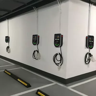
Zeconex EV chargers
3.3 Clamping diode on the primary side of the converter
Since the voltage oscillation of the rectifier diode at the secondary side leads to the increase of common mode EMI emission, adding two clamp diodes at the primary side of the conventional full-bridge DC/DC converter can suppress the voltage ringing phenomenon of the rectifier diode at the secondary side of the converter, which can reduce the common mode EMI emission. The two clamp diodes connected to the transformer can be divided into two cases: Trlead type and Trlag type. In this article, the clamping diodes are connected to the main transformer in a similar way to the Trlead type, but not the same. The phase-shifted ZVS-DC/DC full-bridge converter with complementary voltages operates with two clamping diodes, each acting twice in one operating cycle. To analyze the clamp diode VD6, the converter super-arm power switching tube at the moment of the shutdown, the clamp diode conducts, this process is defined as the clamp A mode, the power switching tube at the end of the zero states, the clamp diode will be in the conductive once, this process is defined as the clamp B mode, the role of the clamp diode of the two processes is not the same.
Due to the role of capacitor CA, the auxiliary transformer and the main transformer voltage are complementary forms, when the clamp diode is conducted, the voltage on the auxiliary transformer will be added to the inductor Lr so that the current is increasing. The junction capacitance of the output rectifier diode will be continuously charged, and when the voltage reaches half of the input voltage, the voltage at point C of the converter will be zero, and at this time the clamp diode will conduct again so that the voltage on the main transformer will remain the same as the input voltage, which will make the voltage spike of the output rectifier diode significantly improved and reduce voltage oscillation.
Unlike the traditional Trlead type, the current flowing through the lagging arm of the converter is not always constant in the clamped A mode, the voltage on the auxiliary transformer will make the current increase continuously so that the power switching tube in the lagging arm can have enough energy to achieve ZVS. The clamping diode not only achieves the ZVS of the lagging tube in a better way but also reduces the voltage oscillations of the rectifying diode on the secondary side of the converter, thus suppressing the common mode EMI. The clamping diode not only achieves better ZVS of the lagging tube but also reduces the voltage oscillation of the rectifier diode on the secondary side of the converter, thus suppressing the common mode EMI and making the converter more EMC compatible.
Simulation Analysis
To verify the correctness of the common-mode EMI suppression method, the DC/DC converter circuit is built after the suppression measures are taken, and reasonable simulation conditions are set to simulate and analyze it. Common-mode interference current waveform on the high-voltage DC side after the suppression method. The common-mode interference current of the DC/DC converter fluctuates up and down within 0.5 mA after suppression, and the spike current decreases to 1.3 mA at most, and the common-mode interference current is significantly reduced after the suppression measures are taken.
Common mode interference current spectrum of the high voltage DC side after suppression. Comparing the spectrum of the common-mode interference current before and after suppression, it can be seen that the spectral amplitude of the common-mode interference current decreases by 10 dBμA to 25 dBμA. Overall, the suppression measure significantly reduces the spectral amplitude of the common-mode interference current, and the spectral amplitude of the interference current at most of the frequency points is lower than the peak value of the conduction interference current provided by the IEC61851 standard, which weakens the common mode EMI impact of the DC/DC converter system on other systems of the charger. This weakens the common mode EMI effect of the DC/DC converter system on the rest of the charger.
The common mode interference voltage waveform on the HVDC side after suppression can be measured from the LISN measurement terminal, and the common mode interference voltage fluctuates within the range of 0.05 V, with a maximum interference voltage of 0.13 V. The corresponding frequency spectrum of the interference voltage on the HVDC side. Comparative analysis before and after suppression shows that the common mode conducted interference voltage spectrum amplitude has decreased by 17 dBμA to 30 dBμV on average, and the common mode electromagnetic interference voltage spectrum amplitude is lower than the peak value of broadband conducted electromagnetic interference in the IEC 61851 standard, so the DC/DC converter meets the EMC requirements of electric vehicle chargers after the suppression method is adopted.
Conclusion
By analyzing the working principle of the DC/DC converter and the common mode EMI generation mechanism in an electric vehicle charger, a voltage complementary passive auxiliary network phase-shifted ZVS-DC/DC full-bridge converter with clamp diode is designed to weaken the ability of the converter to propagate the common mode EMI to the outside. Simulation experiments are conducted before and after the suppression method is adopted for the DC/DC converter, and the results show that the common-mode EMI generated by the converter after the suppression method is adopted is significantly reduced, which illustrates the effectiveness of the suppression method and makes the EMC of the electric vehicle charger greatly improved, and improves the electromagnetic environment of the charger. In addition, the method does not add additional EMI filters, which saves the cost of the EV charger.
